Contents
The study of Physics Topics involves the exploration of matter, energy, and the forces that govern the universe.
What is Alternating Current? What is the Difference Between a Dynamo and an Electric Motor?
Direct Current Or DC And Alternating Current Or AC
Before discussing alternating current thoroughly, it would be helpful to recapitulate on direct current in short.
Direct current(dc) : In electrochemical cell, the electrical nature of the positive and negative electrodes remains unchanged, i.e., it does not vary with time. Current in a circuit from this cell always remains unidirectional. This kind of current is known as direct current or unidirectional current. However, in spite of being unidirectional, the magnitude of the current may decrease or increase with time. In Fig., the graphs of different kinds of direct current with respect to time are shown. Of these, the current shown in the Fig.(a) is steady current—the magnitude of current in this case always remains unchanged.

Alternating current (ac) : An electrochemical cell can not provide large amounts of electrical energy. All electric power plants use a machine called dynamo or generator for this purpose. The characteristics of this machine are—the electrical nature of its two electrodes does not remain constant, but changes from positive to negative, and from negative to positive periodically.
As a result, current through the external circuit connected to this source gets reversed periodically, i.e., the flow of current does not remain unidirectional. The electromotive force obtained from this source is called alternating emf and the current in the circuit is called alternating current. All modern electrical appliances, simple or delicate, are ac-enabled. Hence is the importance of the study of ac.
Current-time graphs of some alternating currents are shown in Fig.

The following characteristics of alternating current are to be noted.
i) An alternating current is of a wave nature.
ii) The magnitude of the current above the time axis is taken as positive, and that below is taken as negative. This implies that the direction of current gets reversed periodically, and at the moment of this transition the instantaneous magnitude of the current becomes zero.
iii) The waveforms of different alternating currents may be different. The waveforms of the three different currents shown are respectively sinusoidal, square, and triangular in shape. Of them, the discussion about the sinusoidal wave form is of particular importance; because, by appropriate mathematical analysis, the square. triangular or any other wave form can be reduced to a combination of a large number of sinusoidal waves.
Source of Alternating Current : AC Dynamo
Almost the entire electrical energy requirement of the present day world is derived from the phenomenon of electromagnetic induction. The machine employing this phenomenon is called dynamo or generator. A conducting coil is set to rotate inside a magnetic field, as a result of which a current is induced in the coil. This is the basic mechanism.
Definition: The machine in which mechanical energy of a rotating conducting coil placed in a magnetic field is converted into electrical energy, is called a dynamo or generator.]
Description: The main parts of an alternating current dynamo is shown in Fig.

N, S: The poles of a strong horse shoe magnet which produces a uniform magnetic field directed from the north to the south pole in the gap between them. Some lines of force are shown in the figure. This magnet is called the field magnet.
ABCD: A rectangular coil called armature is placed in the uniform magnetic field, which usually contains several turns. The coil in this case is made to rotate about the axis normal to the magnetic field; the direction of rotation in this case is as shown in the diagram.
R1, R2: Two smooth brass rings called slip rings. They are connected to the coil at its open ends A and D.
T1, T2: Two carbon brushes fitted to the rings with the help of springs, which keep the brushes pressed against the rings R1 and R2.
L: An electric lamp, to indicate presence of current.
Observation: The lamp L glows as long as the coil rotates. From this, we can infer that, an electric current is flowing through the external circuit attached to T1 and T2. As soon as the rotation of the coil ceases, the current stops and the lamp goes out.
Working principle: When the coil ABCD rotates, the arms AB and CD intersect the magnetic lines of force. As a result, electromagnetic induction takes place. At a certain moment, when the motion of the arm AB is downwards, according to Fleming’s right hand rule, a current will be induced in the direction BA . At the same time due to upward motion of the arm CD, the direction of induced current will be along DC. So, a current will be set up in the direction DCBA in the coil and will flow from T1 to T2 in the external circuit. In this situation T1 and T2 behave as the positive and negative poles of a battery, respectively.
Here, arms BC and AD do not intersect the magnetic lines of force.
When, after half-rotation the positions of the arms AB and CD are interchanged, by applying Fleming’s right hand rule, it is observed that, current is now induced in the direction ABCD. As a result current flows in the second half of rotation from T2 to T1 in the external circuit. Thus, the polarities of T1 and T2 get reversed, reversing the direction of current.
This reversal of the direction of current goes on periodically. Every time the coil crosses its vertical position, the direction of current gets reversed. Hence, this dynamo is called an ac dynamo. Because the heating effect of electric current [αI2, i.e., same for +I and -I) does not depend on the direction of current, the lamp continues to glow as long as the coil rotates. If a dc galvanometer (e.g., a moving coil galvanometer) is placed instead of the electric lamp, no deflection of its pointer would be observed.
Factors affecting the emf and current: The electromotive force, and hence the current is directly proportional to
- area of the coil,
- number of turns of the coil,
- speed of rotation of the coil and
- strength of the magnetic field. So, if any one of them is increased, the emf will also increase. The current however will decrease with increase in resistance of the circuit.
Electric motor: The principle of action of an electric motor is just opposite to that of a dynamo.
A motor is a device in which a current-carrying coil, placed suitably in a magnetic field, rotates on the principle of action of magnets on currents.
Clearly, a motor converts electrical energy of the coil into its mechanical energy.
Differences between dynamo and motor:
| Dynamo | Motor |
| 1. In a dynamo, mechanical energy is converted into electrical energy | 1. In a motor, electrical energy is converted into mechanical energy. |
| 2. Dynamo works on the principle of electromagnetic induction. | 2. Motor works on the effect of magnet on current. |
| 3. The direction of induced emf in a dynamo is obtained from Fleming’s right hand rule. | 3. The direction of rotation of a motor is obtained from Fleming’s left hand rule. |
However, the discussions on both DC and AC motors are beyond our present syllabus.
Variation of Alternating Current
Waveform of alternating current: Let a rectangular coil ABCD be rotating with uniform angular velocity in a uniform magnetic field [Fig.(a)]. The coil is viewed in a way such that only the AD -end of the coil becomes visible. The different positions of this end with respect to time is shown in Fig.(b).

Let the time period of the coil be T. If the coil starts rotating from its vertical position, then at \(\frac{T}{2}\) and T, it again comes to its vertical position. At these moments both AB and CD are moving parallel to the magnetic field. Considering the equation, e = Blvsinθ with θ = 0°, the induced emf and hence the induced current will be zero. On the other hand, at the times \(\frac{T}{4}\) and \(\frac{3 T}{4}\) the coil lies horizontally.
At those positions AB and CD being directed normal to the magnetic field (θ = 90°), the induced current becomes maximum. However, at the time \(\frac{T}{4}\), the direction of current is along DCBA , while at the time \(\frac{3 T}{4}\), it is along ABCD. So, if the current in the first case be taken as ‘positive, then the current in the second case will be negative [Fig.]. This figure clearly shows a sine-wave; this is the wave nature of current, if th coil starts rotating from its vertical position.
On the other hand, if the coil starts rotating from its horizontal position, the current will be a cosine-wave [Fig.(d)]. Note that, both sine and cosine-waves are called sinusoidal waves.
The current completes a cycle of change in a time equal to the time period of rotation of the coil. A complete wave is thus formed in every cycle.
Expression of alternating current: Let a rectangular coil be rotating with uniform angular velocity ω in a uniform magnetic field B. At any moment t, the angle between the nor
mal to the coil and the direction of magnetic field is θ, say [Fig.(a)].
If the area of the plane of the coil is A, the magnetic flux linked with the coil,

Initially, the angle between the normal to the plane of the coil and the direction of the magnetic field = α (say). After rotation for time t, this angle becomes [Fig.(b)],
θ = ωt + α
So, from equation (1) we get, magnetic flux,
ϕ = BAcos(ωt + α) ……. (2)
Hence, the magnitude of the induced emf in the coil of single turn
e = \(\frac{d \phi}{d t}\) = ωBAsin(ωt + α)
For N turns,
e = ωBANsin(ωt + α) = e0sin(ωt + α)
[here, e0 = ωBAN]
If the total resistance of the coil and the external circuit is R, induced current,
i = \(\frac{e}{R}\) = \(\frac{\omega B A N}{R}\)sin(ωt + α) = \(\frac{e_0}{R}\)sin (ωt + α)
= i0sin(ωt + α) … (4)
Phase: The state of alternating current at any moment is expressed by its phase. In equations (3) and (4), (ωt + α) is the phase of the alternating current.
Phase difference: If the phases of two alternating currents are δ1 and δ2, then (δ1 \(\sim\) δ2) is the phase difference of those two currents.
If ω is the same for the two currents, the phase difference becomes (α1 – α2).
Peak value: As – 1 ≤ sin θ ≤ 1, it can be concluded that—
- the maximum and minimum values of the electromotive force are e0 and -e0 respectively.
- accordingly the maximum and minimum values of the current are i0 and -i0.
These magnitudes, e0 and i0 are called the peak values of electromotive force and current.
Dependence of peak value on different factors: It is obvious from equations (3) and (4) that the peak values of emf as well as current depend directly on each of the quantities involved, viz., ω, B, A, N. Moreover, the peak value of current also varies inversely with the resistance (R) of the circuit.
Time period and frequency: The definite time interval in which a complete cycle repeats itself, is called the time period (T) of an alternating current.
If the angular velocity of the coil is ω, then
T = \(\frac{2 \pi}{\omega}\) …. (5)
The number of complete waves produced in unit time, is called the frequency (n) of an alternating current.
So, n = \(\frac{1}{T}\) = \(\frac{\omega}{2 \pi}\) …. (6)
Frequency is the most important quantity in the expression of an ac. It is to be noted that the frequency of domestic electric supply in India is 50 Hz or 50 cycles per second (cps). It indicates that the direction of current is reversed (50 × 2 ) or 100 times per second.
Circuit Symbol of an AC Source
Fig. represents the symbols of an ac source used in a circuit. Any of these symbols may be used for the purpose.

Average Values of Alternating Voltage and Current
Alternating voltage (V) or current (I) always increases, decreases and changes periodically following the functions sin ωt or cos ωt. But the average values of these quantities do not change with time.
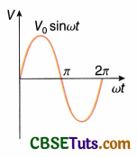
Calculation: Let an expression for sinusoidal alternating voltage,
V = V0sinωt
Average value of it in a full cycle (i.e., for t = T)
= \(\frac{1}{T} \int_0^T V d t\) = \(\frac{1}{T} \int_0^T V_0 \sin \omega t d t\) = 0
This is due to the fact that voltage in a half cycle is positive and in the next half it is of the same magnitude, but negative [Fig.],
For convenience, the average value in a half-cycle, instead of in a full-cycle, in ac is considered as the average value (\(\bar{V}\)) of an alternating voltage.

Similarly, the average value of alternating current,
\(\bar{I}\) = \(\frac{2 I_0}{\pi}\) = 0.637I0
RMS Values of Alternating Voltage and Current
Alternating voltage or current cannot be measured directly with instruments like galvanometers. They can only be measured indirectly following the thermal effect of current.
We know that heat generated in a current carrying conductor is directly proportional to V2 or I2, i.e., heat thus generated does not depend on the direction of current. Due to the periodical changes of an alternating current, the heat in the conductor fluctuates from zero to a certain positive value. Hence the average value of heat should be proportional to the average value of V2 or I2.
The value most commonly used for an ac is its effective value. Effective value of ac is the amount of ac that produces the same heating effect as an equal amount of dc. This is calculated by squaring all the amplitudes of the sine wave over one period, taking the average of these values and then taking the square root. The effective value, being the root of the average (or mean) of square of the currents, is known as the root mean square (in short, rms) value.
Calculation: Let an expression for sinusoidal alternating voltage,

i.e., rms voltage = 70.7% of peak voltage
and rms current = 70.7% of peak current
Relation between peak value, average value and rms value of alternating voltage and current From the above discussion we have,

Similarly, Irms > \(\bar{I}\)
This relation is shown graphically in Fig.

We know that, the heating effect of electric current is directly proportional to I2. Hence ac ammeters and ac voltmeters, are designed on the basis of heating effect of current. They directly measure rms values of alternating current and voltage respectively.
Form factor: The ratio of rms value and average value of alternating voltage or current is known as the form factor.
Thus form factor, f = \(\frac{V_{\mathrm{rms}}}{\bar{V}}\) = \(\frac{\frac{V_0}{\sqrt{2}}}{\frac{2 V_0}{\pi}}\) = \(\frac{\pi}{2 \sqrt{2}}\) = 1.11
Note that, the above value of form factor is applicable only to sinusoidal voltage and current. For different waveforms, the values of form factor are different. For example, for a square wave
Vrms = V0 and \(\bar{V}\) = V0
∴ From the form factor of an alternating voltage or current an effective idea about the waveform can be obtained.
Effects of an AC or DC currents on the human body: The three main factors that determine what kind of shock one experiences are the amplitude, frequency and the duration of the current passing through the body. Direct current have zero frequency i.e., it has a constant amplitude. On the other hand, the peak value of an ac voltage (V0) is \(\sqrt{2}\) times its rms value (Vrms), e.g., a 220 V ac supply is going to 220\(\sqrt{2}\) or 311V (approx.) before coming down to zero. So, one can get a 311V shock from 220V – 50 Hz ac supply line for (50 × 2) or 100 times per second. The calculation indicates the severity of electrocution from ac compared to that from dc of same voltage for the same duration of time.
Numerical Examples
Example 1.
Equation of an ac is I = 10sin(200πt – \(\frac{\pi}{15}\)) ampere. Determine the frequency and peak value of the current.
Solution:
Comparing with the general equation of ac, I = I0sin(ωt + α) we get,
the peak value of current, I0 = 10 A
and angular frequency, ω = 200π HZ
∴ Frequency, n = \(\frac{\omega}{2 \pi}\) = \(\frac{200 \pi}{2 \pi}\) = 100 Hz
Example 2.
If an ac is represented by I = 100 sin 200πt ampere, determine the peak value of current and time period.
Solution:
Comparing with the general equation of ac, I = I0sin(ωt + α) we get,
the peak value of current, I0 = 100 A
and angular frequency, ω = 200π HZ
∴ Time period, T = \(\frac{2 \pi}{\omega}\) = \(\frac{2 \pi}{200 \pi}\) = 0.01 s
Example 3.
An alternating current having peak value 141 A is used to heat a metal wire. To produce the same rate of heating effect, another constant current IA is used. What is the value of I?
Solution:
Irms = \(\frac{I_0}{\sqrt{2}}\) = \(\frac{141 \mathrm{~A}}{\sqrt{2}}\) = 100A
If a steady dc current I produces the same rate of heating, then I = Irms = 100 A.
Example 4.
The peak value of an alternating magnetic Held B is 0.01 T and frequency is 100 Hz. If a conducting ring of radius 1 m is held normal to the held, what emf will be induced in the ring?
Solution:
n = 100 Hz
Time period, T = \(\frac{1}{n}\) = \(\frac{1}{100}\)s
The time taken by the field to increase from 0 T to 0.01 T is \(\frac{T}{4}\) = \(\frac{1}{400}\)s
Now area, A = π ᐧ 12 = π m2
Hence induced emf,
|e| = \(\frac{d \phi}{d t}\) = \(\frac{d}{d t}\)(BA) = A\(\frac{d B}{d t}\)
or |e| = \(\pi\left(\frac{0.01-0}{\frac{1}{400}}\right)\) = 4πV = 12.57V