Contents
The study of Physics Topics can help us understand and solve real-world problems, from climate change to medical imaging technology.
What is the Power Factor of Series LCR Circuit?
Fig. shows the circuit. Alternating voltage applied in the cir-cuit,
V = V0sinωt … (1)

If the instantaneous change in current in the circuit be dI, then the emf induced in the inductor
= \(-L \frac{d I}{d t}\)
On the other hand if Q be the instantaneous charge stored in the capacitor, the opposite emf thus developed in the circuit = –\(\frac{Q}{C}\)
So, effective voltage in the circuit,
Ve = V0 sinωt – L\(\frac{d I}{d t}\) – \(\frac{Q}{C}\)
According to Ohm’s law,
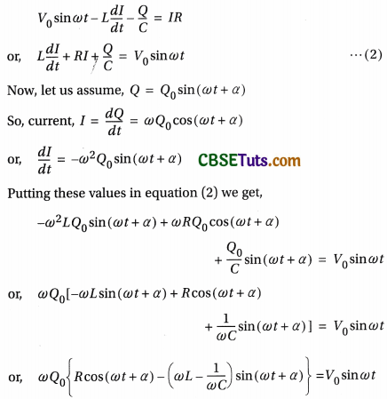

From equations (1) and (3) we conclude,
i) Current lags behind voltage by a phase angle θ where

This phase relation is shown in Fig. Now if VL < VC i.e., ωL < \(\frac{1}{\omega C}\), θ will be negative. In such case, current I leads voltage V by angle θ. Voltage across the resistance R i.e., VR and current I are in the same phase. On the other hand, current I lags behind VL by 90° but leads VC by 90° phase angle.

In Fig., it is clear that if VL < VC i.e., if ωL < \(\frac{1}{\omega C}\), I leads V by an angle θ.
ii) In LCR circuit, Z plays the same role as R in a pure resistive circuit. So, Z is the impedance of the circuit.
Impedance,
Z = \(\sqrt{R^2+\left(\omega L-\frac{1}{\omega C}\right)^2}\) = \(\sqrt{R^2+X^2}\)
where X = ωL – \(\frac{1}{\omega C}\) = XL – XC reactance of the circuit. Impedance in an LCR circuit is the effective resistance of the circuit arising from the combined effect of ohmic resistance and reactance of the circuit.
Fig. shows the impedance triangle for the circuit.

Power in series LCR circuit:
Here, power factor of the circuit, cosθ = \(\frac{R}{Z}\)[Fig.]
Therefore power consumed in the circuit,
P = \(\frac{1}{2} V_0 I_0 \cos \theta\) = \(\frac{1}{2}\left(I_0 Z\right) I_0 \cdot \frac{R}{Z}\) = \(\frac{1}{2} I_0^2 R\) = \(\left(\frac{I_0}{\sqrt{2}}\right)^2 R\)
i.e., P = \(I_{\mathrm{rms}}^2 R\)
This indicates that in this circuit power is dissipated neither in the inductor nor in the capacitor, but in the resistor only.
Hence currents through L or C are wattless.
- The effective resistance of an LCR alternating current circuit is essentially the impedance of that circuit.
- Inverse of impedance is known as admittance. i.e., admittance = \(\frac{1}{Z}\). Its unit is ohm-1 or siemens.
- A pure resistance R opposes the current in any circuit and electrical energy is dissipated through it.
- An inductive reactance XL and a capacitive reactance XC also oppose this current in a circuit, but no energy is dissipated through a pure inductor or a pure capacitor.
- Both XL = ωL and XC = \(\frac{1}{\omega C}\) depend on the frequency ω of the applied voltage. Clearly, for a dc voltage, ω = 0, so that XL = 0, but XC = ∞. This means that dc passes freely through a pure inductor, but is totally blocked by a pure capacitor, which acts like an open switch.
- Units of impedance and reactance: Both quantities have the same unit ohm (Ω).
Advantages of the capacitor dependent regulator over a resistor dependent regulator: In a resistor dependent regulator the resistance also dissipates some energy which heats up the regulator. On the other hand, only a capacitor but no resistor is used in an electronic regulator. Current in the circuit can he changed by regulating the capacitance of the capacitor and hence the speed of an electric fan can be controlled at will. As the current flowing through a pure capacitive ac circuit is wauless, such a regulator almost does not dissipate any power. So power is saved more in a capacitor dependent regulator than in a resistor dependent regulator. An electric regulator is useful in many devices—running of an electric fan is just one of them.


Series resonance: It is observed from equation (4) that for ωL = \(\frac{1}{\omega C}\), the denominator becomes minimum and hence the current I will be maximum. This phenomenon is called series resonance of LCR circuit. If f0 be the frequency for which the circuit reaches the above state, the condition for resonance, then

This frequency f0 is called resonant frequency. The particular frequency olcurrent in an LCR serles circuit for which Inductive reactance (XL) and capacitive reactance (XC) become equal lo each other is called resonant frequency. Under this condition the circuit is termed as resonant circuit. Thus, whatever be the value of frequency other than f0, current I i.e., Irms is always less than its maximum value Im. The change of ac with angular frequency in an LCR circuit is shown graphically [Fig.]. It is known as resonance curve. As Im = \(\frac{V_0}{R}\), Im increases with the decrease of R.
Properties:
i) In case of resonance,
ω0L = \(\frac{1}{\omega_0 C}\) or, XL = XC
which indicates that the inductive and capacitive reactances balance each other. And hence the circuit becomes equivalent to a pure resistive circuit.
ii) According to equation (5), for resonance,
tanθ = \(\frac{0}{R}\) = o or, θ = o
i.e., in resonance circuit, alternating voltage V and alternating current I are in equal phase. In this condition, according to equation (4) the maximum value of I0 i.e., Im = V0/R, which is equivalent to a pure resistive circuit.
iii) LCR series circuit finds use in the receiver of a radio set. The resonant frequency of this LCR circuit is tuned with the frequency of the signal transmitted from a radio station. Hence resonance occurs. As a result the magnitude of current increases a lot and the transmitted signal can easily be received. LCR series circuit is also known as acceptor dr-
cuit.
Sharpness of resonance and Q-factor: Power consumed at LCR series circuit,
P = \(\frac{1}{2} V_0 I_0 \cos \theta\)
where cosθ = power factor = \(\frac{R}{Z}\)
∴ P = \(\frac{1}{2} V_0 I_0 \cdot \frac{R}{Z}\) = \(\frac{1}{2} V_0 \cdot \frac{V_0}{Z} \cdot \frac{R}{Z}\)
= \(\frac{1}{2} V_0^2 \frac{R}{R^2+\left(\omega L-\frac{1}{\omega C}\right)^2}\) …….. (8)
At resonance, ω = ω0 and ω0L = \(\frac{1}{\omega_0 C}\), and as a result power dissipation becomes maximum. From equation (8) we come to the value of maximum power dissipation, i.e.,

The Fig. shows the average power (P) versus frequency (ω) curve using the same circuit parameters used in Fig. The points A and B in Fig. have some special importance. Each of these points denote half maximum power \(\left(\frac{P_m}{2}\right)\)
The rapidity with which resonance phenomena arise and then disappear is a measurement of the sharpness of resonance. Resonance will he sharp if the value of bandwidth (Δω) is small. This is of course possible only when the resonance curve falls steeply around ω = ω0.
Putting P = \(\frac{P_m}{2}\) in equation (1o) we get,

But we have \(\omega_0^2\) = \(\frac{1}{L C}\) (from series resonance condition)
Therefore from equation (11),
ω2 – \(\omega_0^2\) = \(\pm \frac{R}{L} \omega\)
i.e., ω2 – \(\frac{R}{L} \omega\) – \(\omega_0^2\) = 0 and ω2 + \(\frac{R}{L} \omega\) – \(\omega_0^2\) = 0
Solving these quadratic equations neglecting the negative values of ω we get,
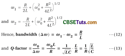
Q- factor measures the sharpness of resonance in an LCR circuit. Inevitably, as Δω goes lesser, Q-factor becomes greater and so resonance becomes more sharp.
From equation (13), Q = \(\frac{\omega_0 L}{R}\) = \(\frac{X_L}{R}\) = \(\frac{I X_L}{I R}\) = \(\frac{V_L}{V_R}\)
where VL = voltage difference across inductor
and VR = voltage difference across resistor
At resonance, VR = applied voltage (V)
and VL = VC [VC = voltage difference across capacitor]
∴ Q = \(\frac{V_L}{V}\) = \(\frac{V_C}{V}\)
i.e., voltage difference (also called voltage drop) across inductor or capacitor with respect to applied voltage in LCR series circuit is termed as Q-factor of the circuit.
The Q -factor is often much grater than 1. This means that in a series resonant circuit, VL and VC are much greater than the applied voltage V. This signifies a prominent voltage amplification across the inductor L and capacitor C.
Q -factor is a dimensionless parameter, which denotes the degree of damping of a resonator or oscillator. The more the value of Q, the less is the rate of dissipation of energy with respect to the energy stored and less is the damping of the oscillator.
Numerical Examples
Example 1.
In an LCR series ac circuit R = 10Ω, L = 50 mH and C = 5µF. Find out the resonant frequency and Q -factor. Find also the bandwidth and half-power frequencies.
Solution:

Example 2.
In an LCR series combination, R = 400 Ω, L = 100 mH and C = µF. This combination is con
nected to a 25 sin 2000 t volt source. Find
(i) the Impedance,
(ii) peak value of current,
(iii) phase difference of voltage and current,
(iv) power factor and
(v) dissipated power In the circuit.
Solution:
Applied ac voltage, V = 25 sin 2000t volt
∴ Peak value of voltage, V0 = 25V;
angular frequency, ω = 2000 Hz
and L = 100 mH = 0.1H
So, ωL = 2000 × 0.1 = 200Ω
Here, C = 1μF = 10-6F So, \(\frac{1}{\omega C}\) = \(\frac{10^6}{2000}\) = 500Ω
i) Impedance of th circuit,
Z = \(\sqrt{R^2+\left(\omega L-\frac{1}{\omega C}\right)^2}\)
= \(\sqrt{(400)^2+(200-500)^2}\) = 500Ω
ii) Peak value of Current, I0 = \(\frac{V_0}{Z}\) = \(\frac{25}{500}\) = 0.05A
iii) If the phase difference of voltage and current be θ then,
tanθ = \(\frac{\omega L-\frac{1}{\omega C}}{R}\) = \(\frac{200-500}{400}\) = \(-\frac{3}{4}\) = tan(-36.9°)
i.e., current leads voltage by a phase angle of 36.9°.
iv) Power factor of the circuit,
cosθ = \(\frac{R}{Z}\) = \(\frac{400}{500}\) = 0.8
v) Power dissipated,
P = \(\frac{1}{2} V_0 I_0 \cos \theta\) = \(\frac{1}{2}\) × 25 × 0.05 × 0.8 = 0.5W
Example 3.
Power factor of an L R circuit is \(\frac{1}{\sqrt{2}}\). If the frequency of ac is doubled, what will be the pwer factor?
Solution:

Example 4.
If the value of inductor L is 1 mH and the applied ac source frequency is 50 Hz, find the inductive reactance in the above case. [WBCHSE Sample Question]
Solution:
Here, L = 1 mH = 1o-3 W
and ω = 2πf = 2 × 3.14 × 50 = 314 Hz
∴ XL = ωL = 314 × 10 = 0.314 Ω
Example 5.
A series LC circuit has L = 0.405 H and C = 25 μF. The resistance R is zero. Find the frequency of resonance. [WBCHSE Sample Question]
Solution:
Here, L = 0.405 H, C = 25 μF = 25 × 10-6 F
∴ fr = \(\frac{1}{2 \pi \sqrt{L C}}\) = \(\frac{1}{2 \times 3.14 \times \sqrt{0.405 \times 25 \times 10^{-6}}}\) = 50 Hz
Example 6.
An inductor and a capacitor of reactances 25Ω and 75Ω, respectively, are connected across a 250 V ac source in series.

Find the potential difference across the inductor and the capacitor. Establish their relationship with the main voltage.
Solution:
Impedance of the series circuit having capacitor and inductor,
Z = XC – XL = (75 – 25)Ω = 50Ω
So current, I = \(\frac{250}{50}\) = 5 A
Potential difference across the inductor,
VL = 5 × 25 V = 125 V
and potential difference across the capacitor,
VC = 5 × 75 V = 375 V
Now, main voltage,
V = 250 V
Hence, the relationship between V, VL and VC is
V = VC – VL
Example 7.
A capacitor, a resistor of 5Ω and an inductor of 50 mH are in series with an ac source marked 100 V, 50 Hz. It is found that the voltage is in phase with the current. Calculate the capacitance of the capacitor and the impedance of the circuit.
Solution:
Since both voltage and current of the circuit are in the same phase, the circuit is purely resistive. So impedance of the circuit, Z = R = 5
Frequency of the resonent circuit,
f = \(\frac{1}{2 \pi \sqrt{L C}}\)
∴ C = \(\frac{1}{4 \pi^2 L f^2}\) = \(\frac{49}{4 \times 484 \times 50 \times 10^{-3} \times 50 \times 50}\)
= 2.03 × 10⁻⁴F
Hence, the capacitance is 2.03 × 10⁻⁴ F and the impedance is 5Ω.
Example 8.
A capacitor and a resistor are connected in series with an ac source. If the potential differences across C, R are 120 V, 90 V respectively and if the rms current of the circuit is 3 A, calculate
(i) the impedance and
(ii) the power factor of the circuit. [CBSE ’06]
Solution:
Alternating voltage in the circuit,
V = \(\sqrt{V_R^2+V_C^2}\) = \(\sqrt{90^2+120^2}\) = 150 V
Now, current through the circuit, I = 3 A
(i) Impedance of the circuit, Z = \(\frac{V}{I}\) = \(\frac{150}{3} \Omega\) = 50Ω
(ii) Power factor of the circuit, cosθ = \(\frac{V_R}{V}\) = \(\frac{90}{150}\) = 0.6
Example 9.
A 200µF capacitor is in series with a 50Ω resistor and is connected to a 220 V, 50 Hz ac source.
(i) What is the maximum current in the circuit?
(ii) What is the difference in time when the current and the voltage attain maximum values?
Solution:
Angular frequency of the source,
ω = 2πf= 2 × 3.14 × 50Hz C
= 200µF = 2 × 10⁻⁴F
Maximum current passing through the circuit,

If the voltage and the current attain maximum value at a time difference of t, then
θ = ωt
or, t = \(\frac{\theta}{\omega}\) = \(\frac{17.67 \times \pi}{180 \times 2 \pi \times 50}\) = 9.82 × 10⁻⁴s
Example 10.
A resistor, R = 300Ω and a capacitor, C = 25μF are connected in series with an ac source. The peak value of voltage (V0) and the frequency (f) of the source are 150 V and \(\frac{50}{\pi}\) Hz respectively. Find the peak value of current and the power dissipated in the circuit.
Solution:
If ω is the angular frequency of the ac source, then
\(\frac{1}{\omega C}\) = \(\frac{1}{2 \pi \times \frac{50}{\pi} \times 25 \times 10^{-6}}\) = 400Ω
Thus peak value of current,
I0 = \(\frac{V_0}{\sqrt{R^2+\frac{1}{\omega^2 C^2}}}\) = \(\frac{150}{\sqrt{300^2+400^2}}\) = 0.3 A
Hence, power dissipated in the circuit
= \(\frac{1}{2} I_0^2 R\) = \(\frac{1}{2}\) × (0.3)2 × 300 = 13.5W
Example 11.
A series LCR circuit containing a resistance of 12011 has angular resonance frequency 4 × 10⁵ rad/s. At resonance, the voltages across resistance and inductance are 60 V and 40 V, respectively. Find the values of L and C. At what frequency, does the current in the circuit lag behind the voltage by 45° ?
Solution:
At resonance, XL = XC
∴ I = \(\frac{V_R}{R}\)
= \(\frac{60}{120}\) [∵ voltage across the resistance, VR = 60 V]
= 0.5 A
Now, voltage across the inductor,
VL = IXL = IωL
or, L = \(\frac{V_L}{I \omega}\) = \(\frac{40}{0.5 \times 4 \times 10^5}\)
[∵ angular frequency, (ω = 4 × 10⁵ rad/s]
= 2 × 10⁻⁴ H
We know that at resonance,
XL = XC or, ωL = \(\frac{1}{\omega C}\)
or, C = \(\frac{1}{\omega^2 L}\) = \(\frac{1}{\left(4 \times 10^5\right)^2 \times 0.2 \times 10^{-3}}\) = 3.125 × 10⁻⁸F
Let the angular frequency be ω1 when the current lags behind the voltage by 45°.

The physically meaningful solution of the above equation is,
ω1 = \(\frac{6 \times 10^5+10 \times 10^5}{2}\) = 8 × 10⁵ rad/s
Example 12.
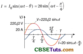
In an LR series circuit, a sinusoidal voltage V = V0sin ωt is applied. It is given that L = 35 mH, R = 11Ω, Vrms = 220V, \(\frac{\omega}{2 \pi}\) = 50 Hz and π = \(\frac{22}{7}\). Find the amplitude of current in the steady state and obtain the phase difference between the current and the voltage. Also plot the variation of current for one cycle on the given graph.

Solution:
Inductive reactance,
XL = ωL = (2π)(50)(35 × 10-3) ≈ 11Ω
Impedance, Z = \(\sqrt{R^2+X_L^2}\) = \(\sqrt{11^2+11^2}\) = \(11 \sqrt{2} \Omega\),
Given Vrms = 220 V
Hence, amplitude of voltage, V0 = \(\sqrt{2} V_{\mathrm{rms}}\) = \(220 \sqrt{2} \mathrm{~V}\)
∴ Amplitude of current, I0 = \(\frac{V_0}{Z}\) = \(\frac{220 \sqrt{2}}{11 \sqrt{2}}\) = 20A
Phase difference between the current and the voltage in the circuit,
θ = tan-1\(\left(\frac{X_L}{R}\right)\) = tan-1\(\left(\frac{11}{11}\right)\) = \(\frac{\pi}{4}\)
In LR circuit, voltage leads the current by phase angle θ. Thus current in the circuit,